- Home
-
- Industries
-



Standard elastomeric and polymeric seals inevitably fail under extreme temperatures, high vacuum, or aggressive chemical exposure. When operating environments push beyond the safe limits of conventional rubber, engineering reality demands a fundamentally more robust approach. Transitioning to a Metal Seal requires a major shift in understanding how the mating interface is actually achieved. We must move away from relying on simple elastomeric compression. Instead, we must design for precise plastic deformation combined with continuous elastic springback.
This comprehensive guide unpacks the physical mechanics underlying these high-performance components. You will learn the exact evaluation criteria necessary to specify the proper profile, plating material, and seating load requirements. By applying these engineering principles, you can ensure long-term reliability in critical applications without unnecessarily over-engineering your hardware.
Key Takeaways
A metal seal works by generating a continuous line of contact through plastic deformation of a softer plating layer, backed by the elastic springback of a high-strength metal core.
Selecting the right profile (O-ring, C-ring, E-ring) dictates the required seating load and the seal’s ability to track cavity expansion under thermal cycling.
Hardware preparation is non-negotiable; surface finish and flange rigidity directly dictate the achievable leak rate.
The Physics of the Sealing Interface: Deformation and Springback
How does the interface actually form? When you tighten flange bolts, the compressive force must exceed the yield strength of the seal’s outer plating layer. You force this softer jacket material into the microscopic asperities—the tiny peaks and valleys—of the hardware surface. This action creates a continuous, impermeable barrier. Rubber achieves this through simple elastic compression. Metals require deliberate plastic deformation to block leak paths.
Elastic Core vs. Plastic Jacket
We rely on a dual-action mechanism to ensure reliability. You need both a plastic jacket and an elastic core. The jacket deforms permanently. It flows into the groove imperfections to block potential leak paths. Typical jacket materials include silver, nickel, or gold. Meanwhile, the inner core maintains constant elastic tension. Engineers typically specify high-strength alloys like Inconel 718 for this core. We call this outward tension "springback." It pushes continuously against the flanges. This dynamic resistance accommodates micro-movements caused by vibration or thermal cycling.
Seating Load (Y) and Gasket Factor (m)
Engineers evaluate two critical forces during design. First is the seating load, often denoted as the "Y" factor. This represents the immense initial force required to physically flow the plating into the hardware finish. Second is the gasket factor, or "m" factor. This defines the operational force required to maintain the contact line under maximum internal system pressure. You must provide enough bolt torque to satisfy both requirements simultaneously.
Common Mistakes in Load Calculation: Engineers often underestimate the required seating load. They calculate the operational gasket factor but ignore the initial yield force. You must apply enough torque to physically flow the plating. Without this initial deformation, the internal fluid bypasses the barrier entirely.
Thermal and Pressure Energization
Many cross-sections use internal system pressure to their advantage. We call this pressure energization. As internal pressure rises, fluid or gas enters the open cavity of the profile. This forces the metal walls outward. It actively increases the contact stress against the flanges. Thermal expansion works similarly. As system temperatures climb, the alloy expands, tightening the interface further against the rigid cavity walls.
Threshold Criteria: When to Transition from Elastomers to Metal
Standard elastomers operate safely within a narrow thermal window. They typically survive between -50°C and 200°C. Once you step outside this zone, performance degrades rapidly. Rubber becomes highly brittle at cryogenic temperatures. It melts, chars, or extrudes under extreme heat. You must evaluate this performance gap carefully. A properly designed Metal Seal easily spans from deep cryogenic levels (-270°C) up to 1000°C and beyond.
Vacuum and Outgassing Limits
Ultra-High Vacuum (UHV) systems present another hard boundary. Elastomers suffer heavily from outgassing and permeation. They release trapped volatile compounds into the vacuum chamber over time. This phenomenon compromises process integrity in semiconductor manufacturing or mass spectrometry. Metals prevent outgassing entirely. They secure pure, uncontaminated vacuum states required for sensitive analytical equipment.
Aggressive Media and Radiation
Chemical compatibility offers another major threshold criterion. Aggressive media, ionizing radiation, and harsh petrochemicals destroy polymer chains quickly. In aerospace, nuclear power, or aggressive oil and gas environments, you need materials completely immune to chemical attack. High-nickel alloys provide this absolute resistance. They do not swell, degrade, or dissolve when exposed to harsh solvents or radioactive environments.
Long-Term Degradation and Tamper-Evidence
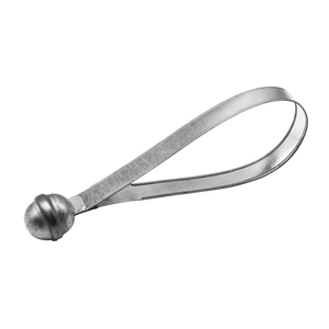
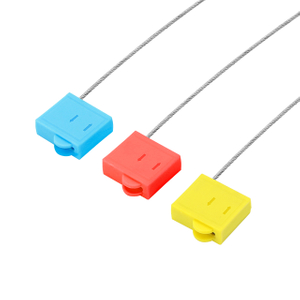
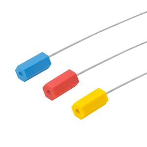
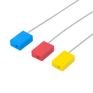
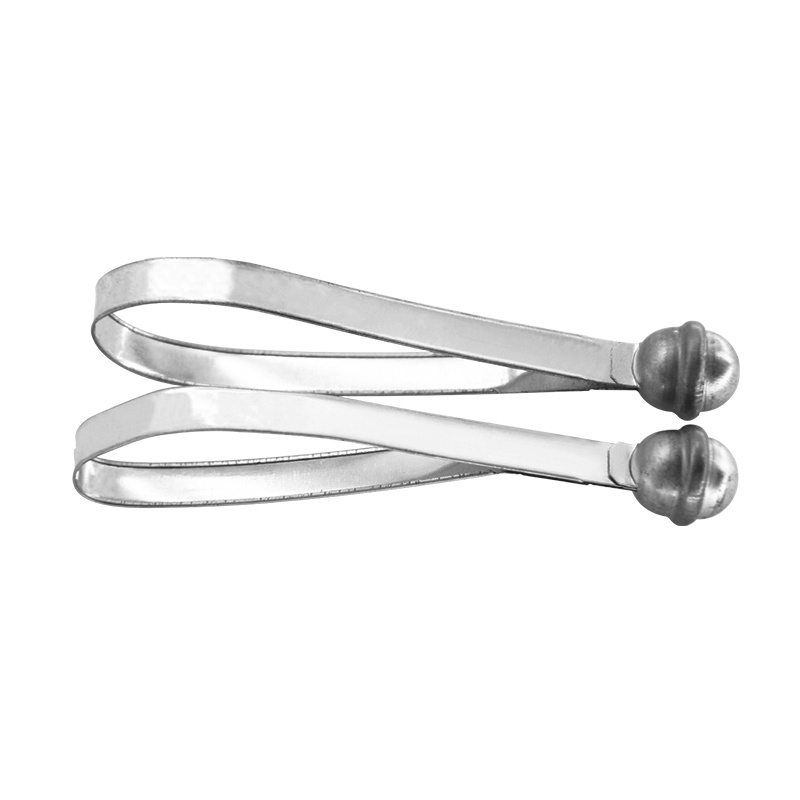
Finally, consider long-term degradation and security needs. Many industrial applications require zero-maintenance longevity over several decades. Utility and field instrumentation setups frequently utilize a meter metal seal for robust, tamper-evident isolation. These mechanical components withstand harsh weather. They prevent unauthorized access effectively. They prove invaluable when long-term environmental resistance is absolutely mandatory.
Best Practices for Media Evaluation: Always verify the chemical compatibility of both the core and the plating. A fluid might ignore the Inconel core but rapidly dissolve a silver jacket. You must consult compatibility charts for the exact media concentration and maximum operating temperature.
Evaluating Metal Seal Profiles for System Integration
Selecting the right profile directly impacts your flange design. Each shape offers a distinct balance of seating load requirements and elastic springback. You cannot swap profiles without recalculating your system parameters.
Profile Categories
Metal O-Rings: These excel in extreme high-pressure and static conditions. They require an exceptionally high seating load to deform their heavy tubular cross-section. Consequently, they offer very low springback. You should specify them only for heavily bolted, highly rigid flanges.
Metal C-Rings: Industry experts consider these the standard for balanced performance. They demand a much lower seating load than O-Rings. They provide significantly higher springback. The open-face design utilizes system pressure to self-energize. This versatility makes them ideal across varied flange conditions.
Spring-Energized Metal Seals: This design combines an outer metallic jacket with an internal helical spring. Specify this profile for systems requiring maximum springback. The internal spring provides robust resistance. They easily compensate for high flange separation or severe thermal cycling transients.
Metal E-Rings and V-Rings: Engineers design these for low-load cavity restrictions. They offer high springback but remain highly sensitive to pressure direction. Handle them carefully. Their thin cross-sections sustain handling damage easily during installation.
Profile Selection Matrix
Profile Type
Seating Load Requirement
Springback Capability
Best Application Scenario
Metal O-Ring
Very High
Low
Static joints, rigid flanges, extreme pressures.
Metal C-Ring
Moderate
High
General high-temp use, pressure-energized systems.
Spring-Energized
Moderate to High
Maximum
Thermal cycling, flange separation risks.
E-Ring / V-Ring
Low
High
Weight-restricted aerospace cavities, low bolt loads.
Critical Specification Dimensions: Hardware and Plating
Hardware preparation remains an absolute, non-negotiable requirement. The chosen plating material shares an explicit correlation with your required flange surface finish. Harder platings require exceptionally smooth hardware to seal properly. If your flanges retain deep machining marks, a soft plating must be thick enough to fill those specific voids.
Understanding Surface Finish Standards
You will frequently see surface finishes denoted in Ra (Roughness Average) or RMS (Root Mean Square). For most metallic installations, you need an Ra of 16 to 32 microinches. If you use a harder nickel plating, you might need an ultra-smooth 8 to 16 Ra finish. Ignoring these finish requirements guarantees a severe leak.
Plating Material Selection Model
Consider this material selection model when specifying your jacket:
Soft / Low-Temperature Platings: Materials like PTFE, Lead, or Indium. They require minimal compressive load. They work perfectly for cryogenic to moderate thermal environments.
Standard High-Temperature Platings: Silver and Gold dominate this category. They offer excellent flow characteristics. They maintain high oxidation resistance at elevated temperatures, making them highly versatile.
Extreme Environment Platings: Nickel and Copper. These require massive seating loads to achieve plastic deformation. However, they survive the maximum possible temperature ranges found in exhaust systems or gas turbines.
Flange Rigidity and Bolt Stretch
Flange rigidity ultimately determines your success. You must analyze the risk of flange deflection under high bolt loads. If your hardware bends, the gap between mating flanges widens. The component will fail if the hardware cannot maintain uniform compression across the entire circumference. Calculate bolt stretch carefully. Ensure your fasteners do not yield under thermal expansion. Fastener yield instantly eliminates your vital contact stress.
Implementation Realities and Adoption Risks
Many engineering teams misunderstand the fundamental "single-use" rule. Because these components rely on plastic deformation, they are strictly single-use items. The jacket crushes to perfectly match a specific flange asperity pattern. Reusing it exponentially increases your failure risk. The previously crushed plating will never align perfectly with those microscopic grooves a second time.
Handling and Installation Vulnerabilities
Handling vulnerabilities pose another significant operational risk. A single microscopic scratch on the plating during installation can create an unsealable leak path. You must enforce clean-room handling protocols. Technicians should use lint-free gloves. They must employ specialized installation tooling to prevent accidental drops or radial scratches across the sealing face.
Tolerance Stack-up Failures
Tolerance stack-up failures happen frequently during system retrofits. You cannot simply drop a rigid metallic ring into a cavity originally designed for an elastomer O-ring. You must recalculate groove depths from scratch. You must verify tolerance stack-ups across all mating parts. Evaluate your bolt yield strengths thoroughly. Elastomers easily forgive loose tolerances and varying groove depths. Rigid metal alloys absolutely do not.
Conclusion
Specifying a rigid sealing component requires careful balance. You must weigh your available seating load capabilities against your required springback and environmental extremes. Elastomers fail when conditions get tough, but engineered metallic profiles thrive if designed correctly.
Lock in your critical parameters early. Document exact temperature ranges, maximum pressures, and chemical media exposure limits before analyzing cross-sections.
Do not retrofit blindly. Always recalculate groove dimensions and bolt yield strengths before replacing an elastomer.
Enforce strict handling protocols. Ensure technicians understand the single-use nature and extreme scratch sensitivity of these parts.
Consult an application engineer early in your design phase. Request a comprehensive finite element analysis (FEA) on your specific flange-and-seal interface. This rigorous step ensures your hardware delivers the necessary compressive force without deflecting, guaranteeing a secure operational lifespan.
FAQ
Q: Can a metal seal be reused?
A: No, they cannot be safely reused. Their mechanism relies on the permanent plastic deformation of a softer outer plating layer into the microscopic grooves of the mating flange. Once compressed, the plating takes a permanent set. Reusing it compromises the continuous sealing line, drastically increasing the risk of leakage.
Q: How much seating load is required for a metal seal?
A: The required seating load varies heavily based on the specific cross-section profile and the chosen plating material. Generally, they demand significantly higher torque and compressive force than standard elastomers. For example, a heavy-walled O-ring plated with nickel requires massive bolt loads, while a silver-plated C-ring requires comparatively less.
Q: What is the standard leak rate for a metal seal?
A: A properly designed and installed component can achieve ultra-high vacuum integrity. Standard helium leak testing rates often reach 1 x 10^-9 atm cc/sec or better. However, achieving this exact leak rate depends entirely on proper flange surface finish, uniform bolt loading, and pristine plating condition prior to installation.
Q: How do I choose between silver and nickel plating?
A: Base your choice on the maximum operating temperature and your available compressive load. Silver offers excellent plastic flow under moderate loads and high oxidation resistance up to around 450°C. Nickel survives much more extreme temperatures (often exceeding 600°C) but requires a significantly higher seating load to achieve the same plastic deformation.